ABSTRACT:
Corrosion under insulation & fireproofing has become more critical in the industry for a number of reasons. For one, the industry as a whole has become more complex. Chemical, petroleum and food processing facilities to name a few, require more sophisticated equipment, instruments and piping arrangement. Piping and equipment are more difficult to insulate or fireproof requiring highly skilled professionals. Cost cutting is putting inspections and maintenance in jeopardy.
These events can lead to a premature wet insulation system and eventually corrosion to the pipe or equipment. Detecting Corrosion Under Insulation (CUI) & fireproofing prior to serious damage or failure to the process system is imperative. Each year millions of dollars are spent in correcting the failure of pipe and equipment as the result of CUI. This situation shouldn’t be surprising since 95 percent of the failures go undetected until the product begins to seep through the insulation system into the ground or floor.
In the current project Pulsed Eddy Current Testing was used for the purpose of detection of corrosion under fireproofing on vessel skirts in one of the petrochemical industry at singapore. Results indicated minor to moderate corrosion type indications on various vessel skirts. Some of the suspected locations were opened and verified with ultrasonic thickness measurement. Slight difference in results reported by the ultrasonic and PEC was observed. PEC as an intrusive tool succeeded in the inspection of vessel skirts without removing the fireproofing.
PULSED EDDY CURRENT (PEC):
PEC is a technique for inspecting carbon steel objects such as pipes and vessels, without the need for contact with steel surface. PEC can measure percentage variations in steel thickness through any non-conductive and non-magnetic material between sensor and steel surface such as air, insulation material, concrete, plastics, coatings, paint, sea water, marine growth deposits, oil etc.
A PEC measurement has two phases as illustrated in Figures 1 and 2. In the first phase electrical current flows through the transmitter coils of PEC probe. This current generates a magnetic field around the probe known as ‘primary field’.
The Primary field is unaffected by the presence of any non-conducting and non-magnetic material and penetrates undisturbed through to the steel below. In this way, the carbon steel directly beneath the transmitter coils is magnetized. Since the carbon steel is ferromagnetic (i.e. it has a high relative magnetic permeability) only the top layer of the steel is magnetized, as shown schematically in Figure 1.
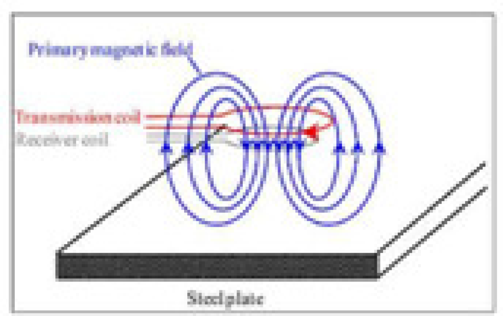
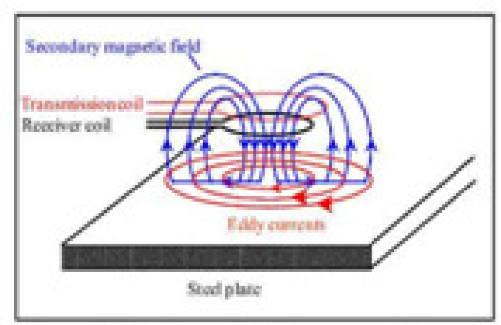
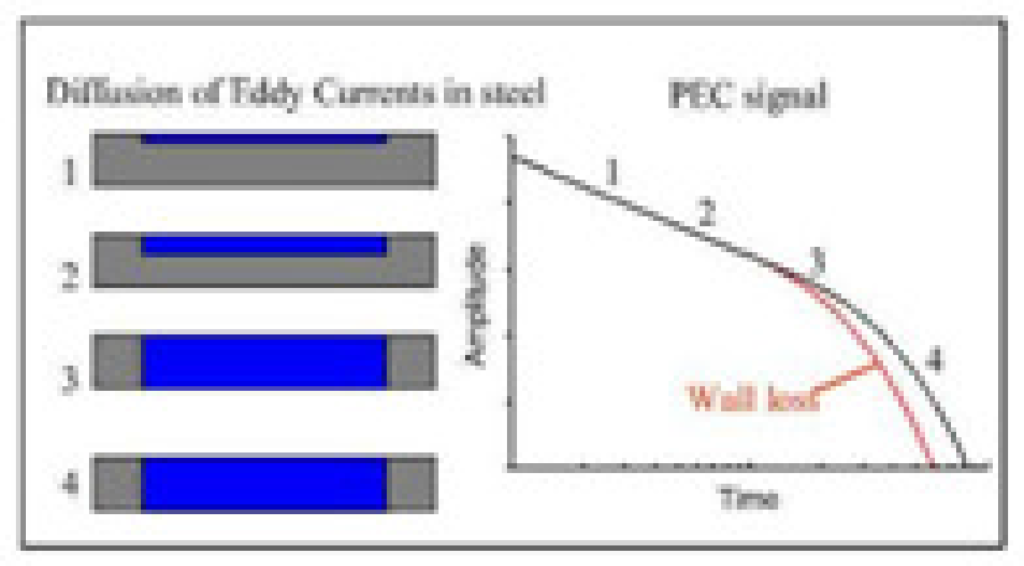
Figure 1: Magnetization of the steel.
Figure 2: Induced eddy currents generate secondary magnetic field in the receiver coil.
Figure 3: Diffusion of eddy currents the onsetof fast decay occurs when the far surface has been reached
In the second phase of measurement the current in the transmitter coil is switched off, collapsing the primary magnetic field. The changing magnetic field induces electrical ‘eddy’ currents in the surface of the steel. These eddy currents generate a secondary magnetic field, Figure 2, which reaches the receiver coils of the PEC probe. The secondary magnetic field induces an electrical voltage in the receiver coils. The magnitude of this voltage as a function of the time is referred to as the ‘PEC signal’.
The PEC signal contains information about the thickness of the steel, as described below. A specimen has a near and a far surface. Initially the eddy currents are confined to the near surface (closest to the PEC probe) but, as time elapses, they travel (or ‘diffuse’) outwards towards the far surface (Figure 3). As long as the eddy currents experience free expansion in the wall, their strength decreases relatively slowly. However, upon reaching the far surface, their strength decreases rapidly. The moment in time where the eddy currents first reach the far surface is indicated by a sharp decrease in PEC signal, known as ‘transition point’ (see Figure 3). The time of the transition point is therefore a measure of wall thickness. For example, the earlier the transition point, the sooner the eddy currents reach the far surface and the thinner the wall must be.
Alternatively, if the transition point occurs later in time, the eddy currents take longer to reach the far surface, so the wall has a larger thickness.
INSPECTION SCOPE & SUMMARY:
In the current project Pulsed Eddy Current Testing was carried out on skirt areas of the following vessels:
Dilution steam generator, Water stripper, Distillate stripper, Fuel Mixing Tower, Quench oil fractionator, Quench water tower, Caustic scrubber, Caustic surge drum, Stage suction drum, Stage discharge drum and dehydrators.


When the equipment is in service, customer wanted to know on the integrity of the base material (skirts) without breaking the fireproofing. PEC is the only technique available in the industry that satisfies above application.
In the first phase of inspection complete data related to the vessels like drawings, thickness and other paramters were collected from the client; thorougly analyzed and site survey was conducted. This exercise helped in finding out critical areas, inaccessible areas and preparing scan plan to carryout inspection in a logical order.
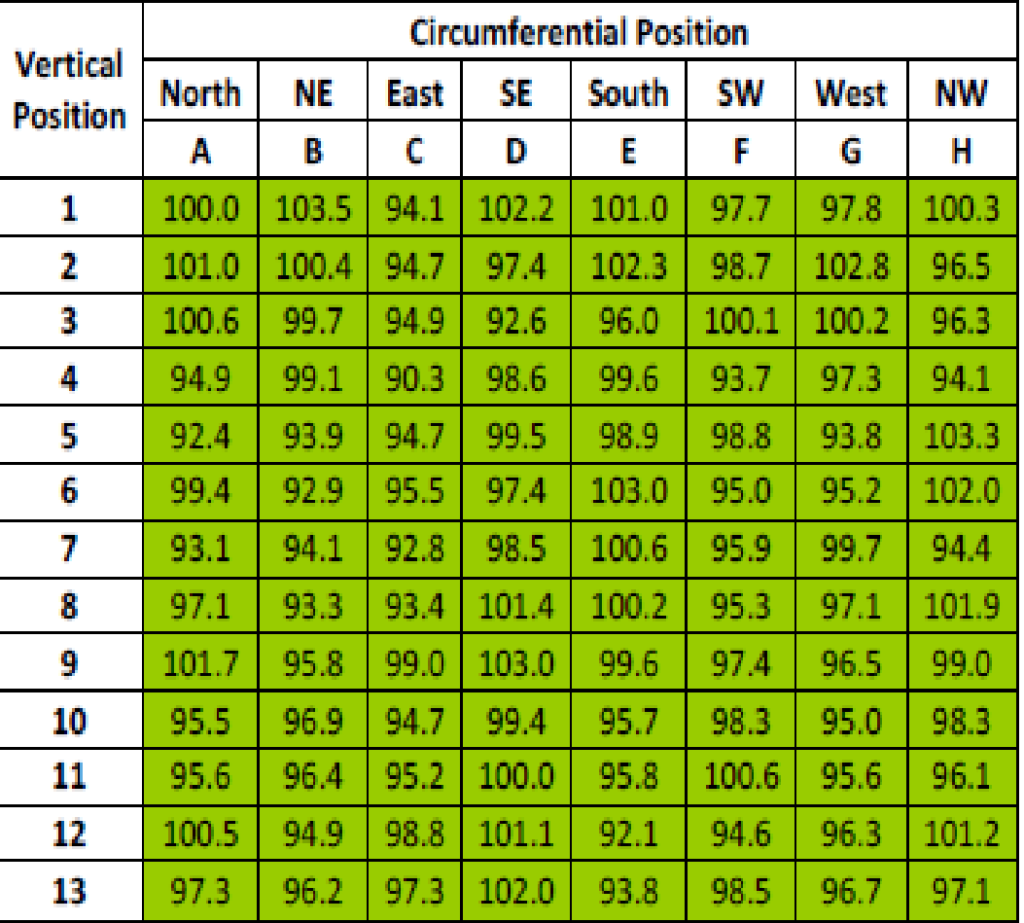
Upon preparation of scan plan, examination areas were marked using grid method & nammed for reference and verification in the future inspections. PEC equipment was prepared; calibration was done as per the procedure and made ready to take measurements in the proposed way of scan plan. PEC measurements were recorded in the percentage of remaining wall thickness with respect to the calibration spot. Results revealed minor to major corrosion type indications on various vessel skirts.
PEC measures average thickness in the footprint area. C-Scan showing color coded percentage remaining wall thickness readings is given in the table. No major corrosion type indications / wall loss measurements were recorded during the inspection.
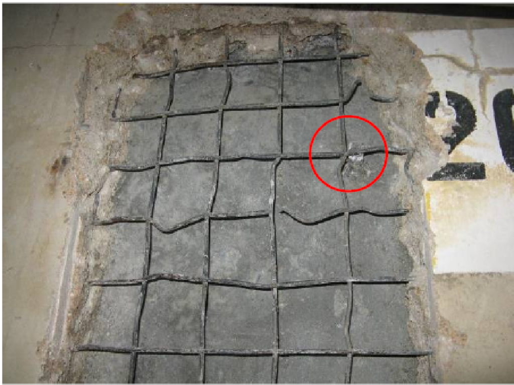
Few locations showing less remaining wall thickness were verified by breaking the concrete. Visual examination with Ultrasonic thickness measurements were performed on these areas. One of which location had foreign material inclusion in the cement which might have caused the permeability changes in the local area showing less remaining wall thickness reading in PEC. Slight variations in the results of PEC were observed against ultrasonic measurements on the other opened areas.
CONCLUSION:
Pulsed Eddy Current Testing has been successfully applied as a technique to inspect vessel skirts without removing fireproofing which saves time and cost. This technique has also proven its efficiency in inspecting concrete coated sphere legs, insulated piping, tanks & other applications without the need to go for conventional method of removing the insulation.